I have recently been troubleshooting some faulty Polaroid SX-70s and I found myself reading back and forth through the repair manual to find the right switch to troubleshoot. So, I decided to create a set of images to help visualize the sequence of steps required to make a photograph with an SX-70. I find it easier to scroll through the steps, or swipe through the steps (clicking on an image enlarges it and allows for swiping or arrowing left and right).
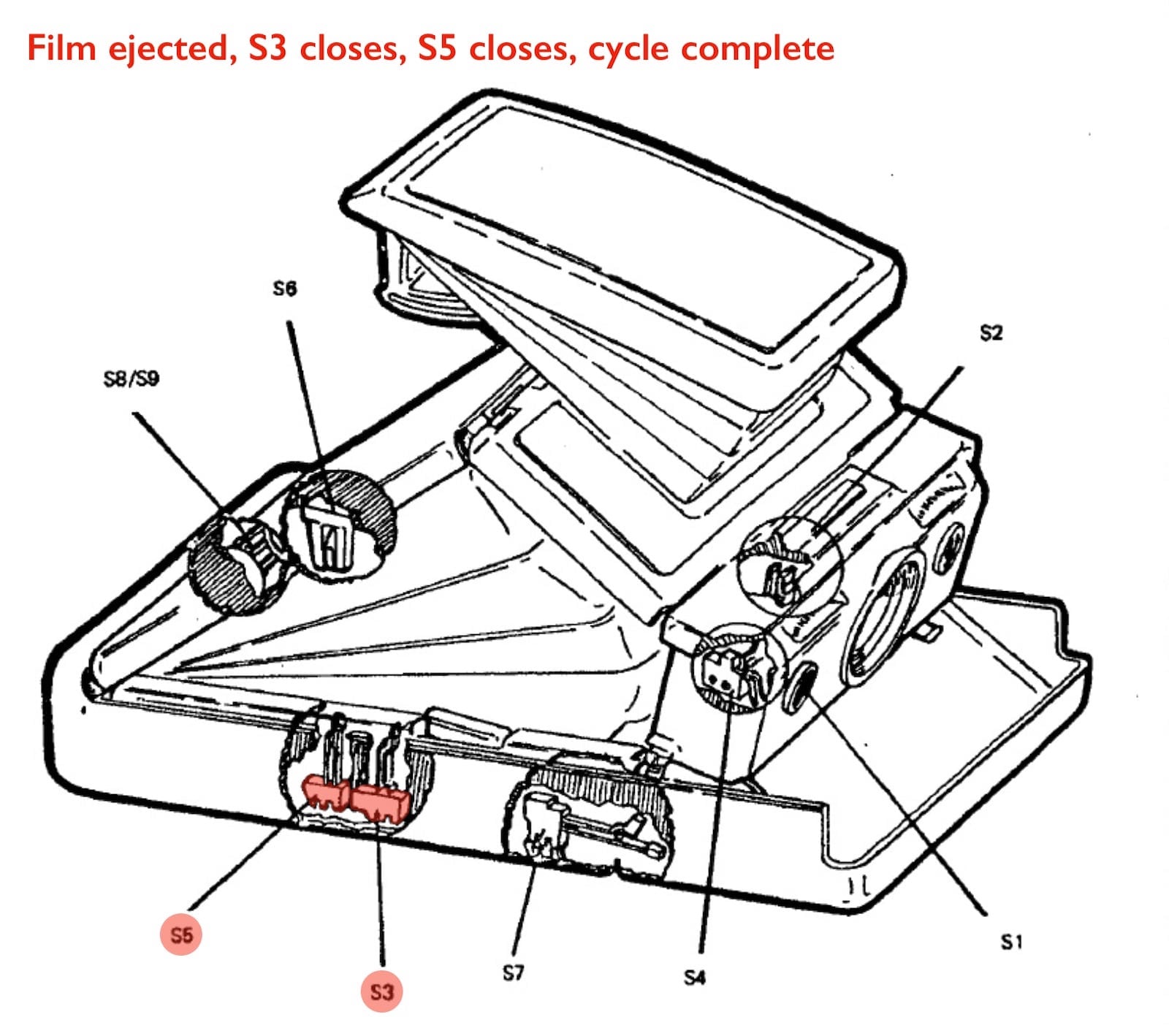
For the camera I was troubleshooting when I made these images, switch 3 was dirty and a little corroded. With S3 not functioning properly the exposure was effectively stuck mid-cycle, the shutter would close and nothing else would happen. After cleaning the drivetrain and the drivetrain switches (S3 and S5) the camera operated normally again.
| Switch | Action | Result |
|---|---|---|
| 1 | Closes | Initiates exposure cycle and causes circuitry to take and deliver the picture. |
| 2 | Closes | Connects circuitry to take flash pictures. |
| 3 | Opens | Initiates "Y", 40 millisecond delay. (Power down solenoid #2 in the flash mode.) |
| 4 | CA Closes | Controls power to solenoid #1 (drops current to holding level). |
| 4 | CB Closes | Signals the ECM to start the motor. |
| 5 | Opens/Closes | Stops motor both by closing and opening depending upon sequence of action and internal circuitry. |
| 6 | Closes | Connects the battery to the electronic circuitry when the camera is opened for use. |
| 6 | Opens | When camera closed, cuts power from battery. |
| 7 | Closes | When S8 is also closed, it provides power to the camera when the front power is latched (for dark side eject). Also acts as an interlock during normal picture taking. |
| 8 | Closes | Enables (with S7 closed) the circuitry to eject dark slide. Opens agan after the dark slide is ejected. |
| 9 | Closes | Prevents firing flash if film pack counter is on "0". |
Prior to capturing an image the photographer must open the camera and load film. That sequence triggers the following switches
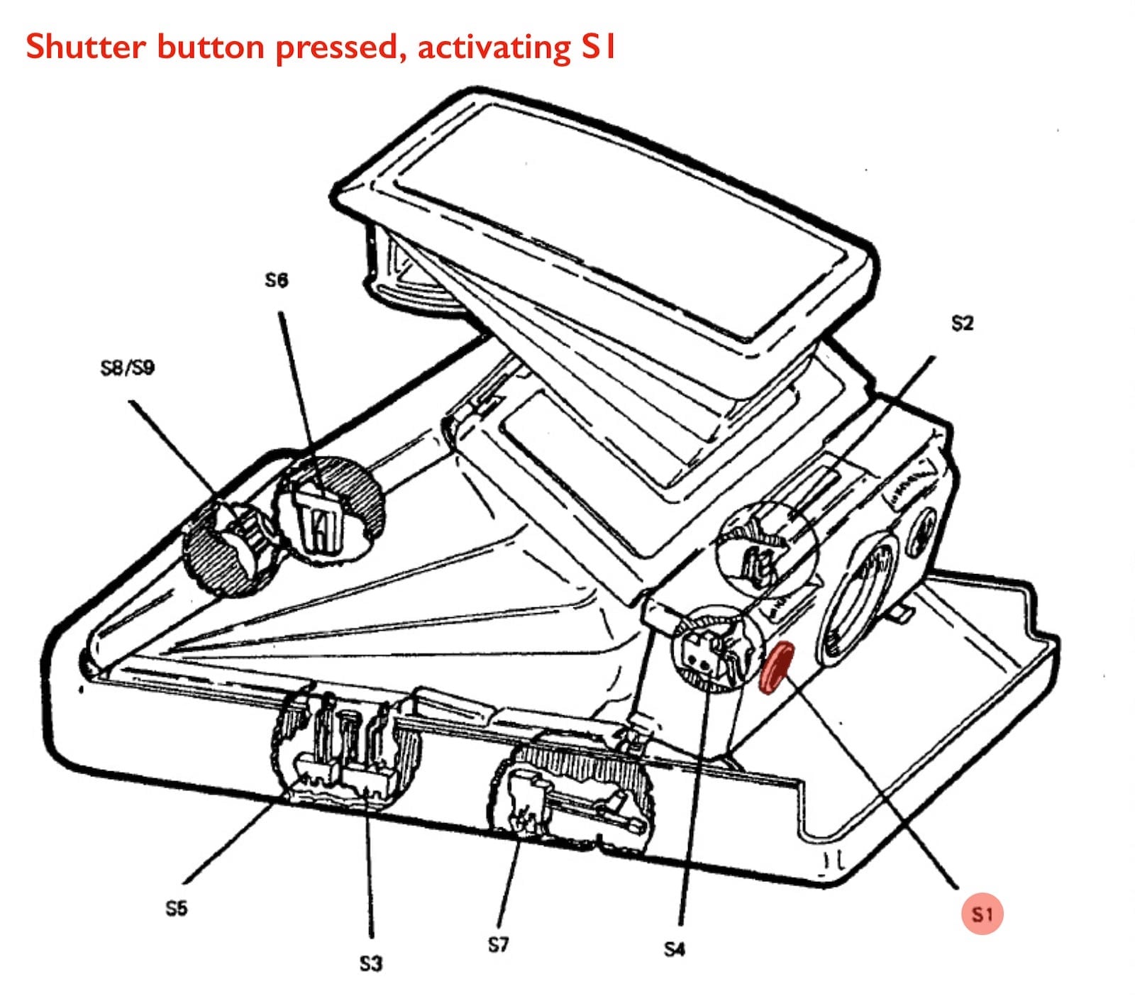
After the preparatory steps are completed the exposure cycle can be triggered by pressing the shutter button.
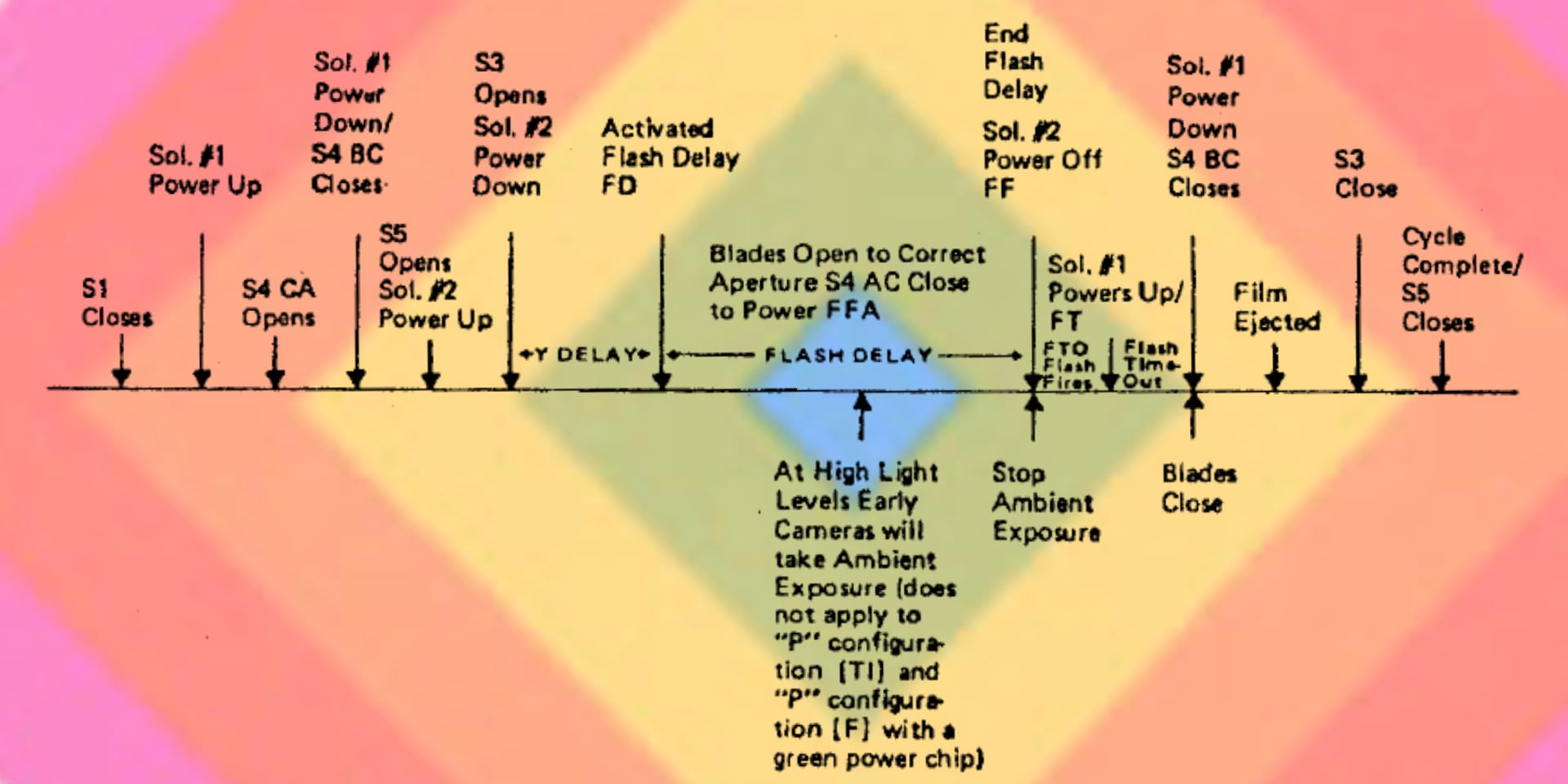
The operator aims, focuses the lens, and presses the red shutter release button (S1). The ECM actuates solenoid #1 which closes the shutter blades.
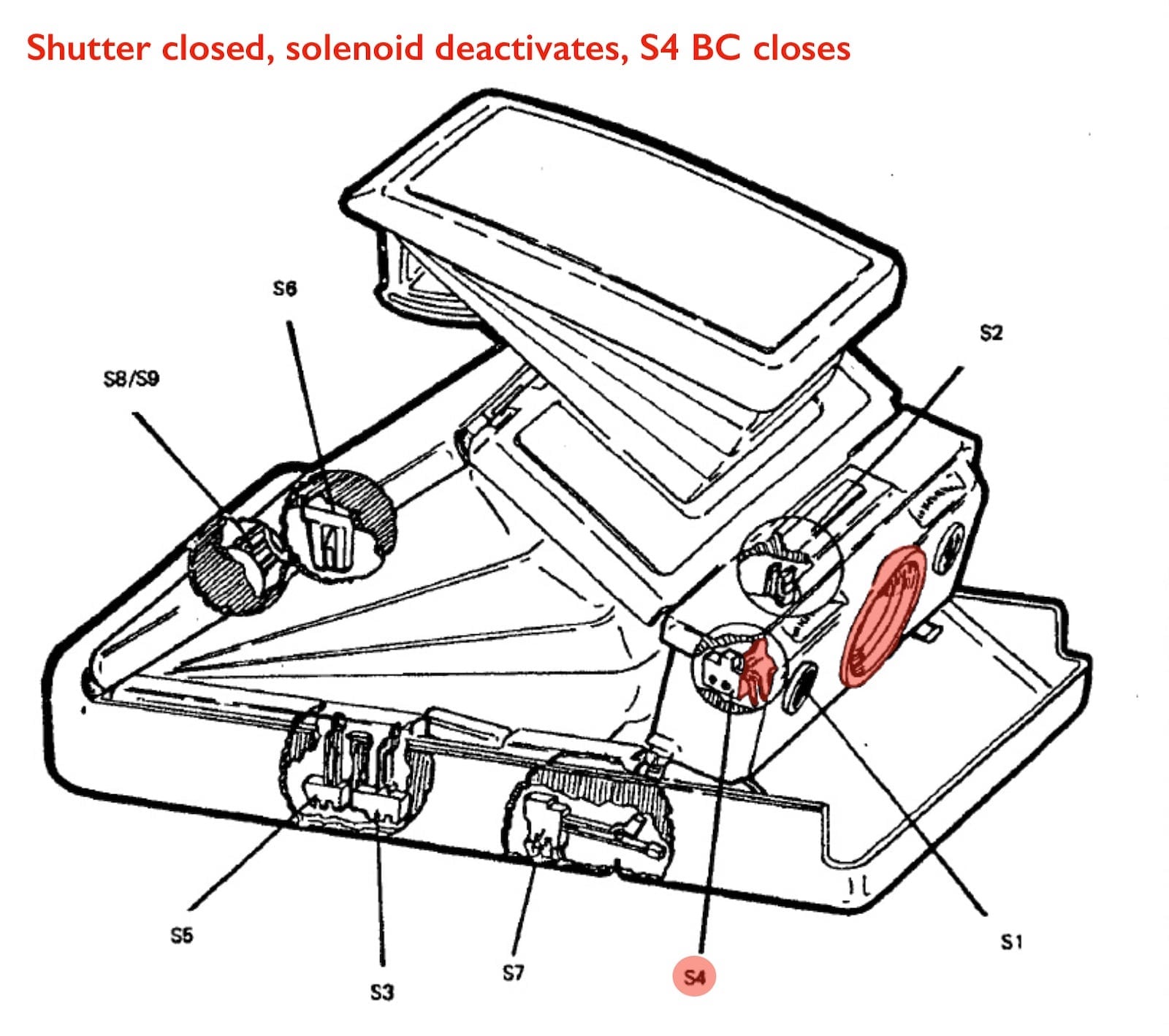
Solenoid #1 transfers the S4 contacts from CA to CB, which in turn switches the circuit from full solenoid power to holding current (power-down). Closing contacts CB of switch S4 also starts the drive motor. Opening S4 (CA) removes power from the FFA.
As the gear train runs, it mechanically releases the spring-loaded fresnel carrier so that it leaves the film plane and rises to its exposure position. This is accomplished by the mirror release cam of the recheck gear. The recock ram falls off the recock cam, allowing the ram to snap forward. This allows the drive spring to raise the fresnel assembly to the exposure mode.
The ram also moves away from S5 allowing S5 to open. This action causes the ECM to dynamically brake the motor which will remain at rest throughout the exposure segment of the cycle. The S5 switch action also programs the ECM to complete the cycle even though the operator has released the exposure button after S5 is open.
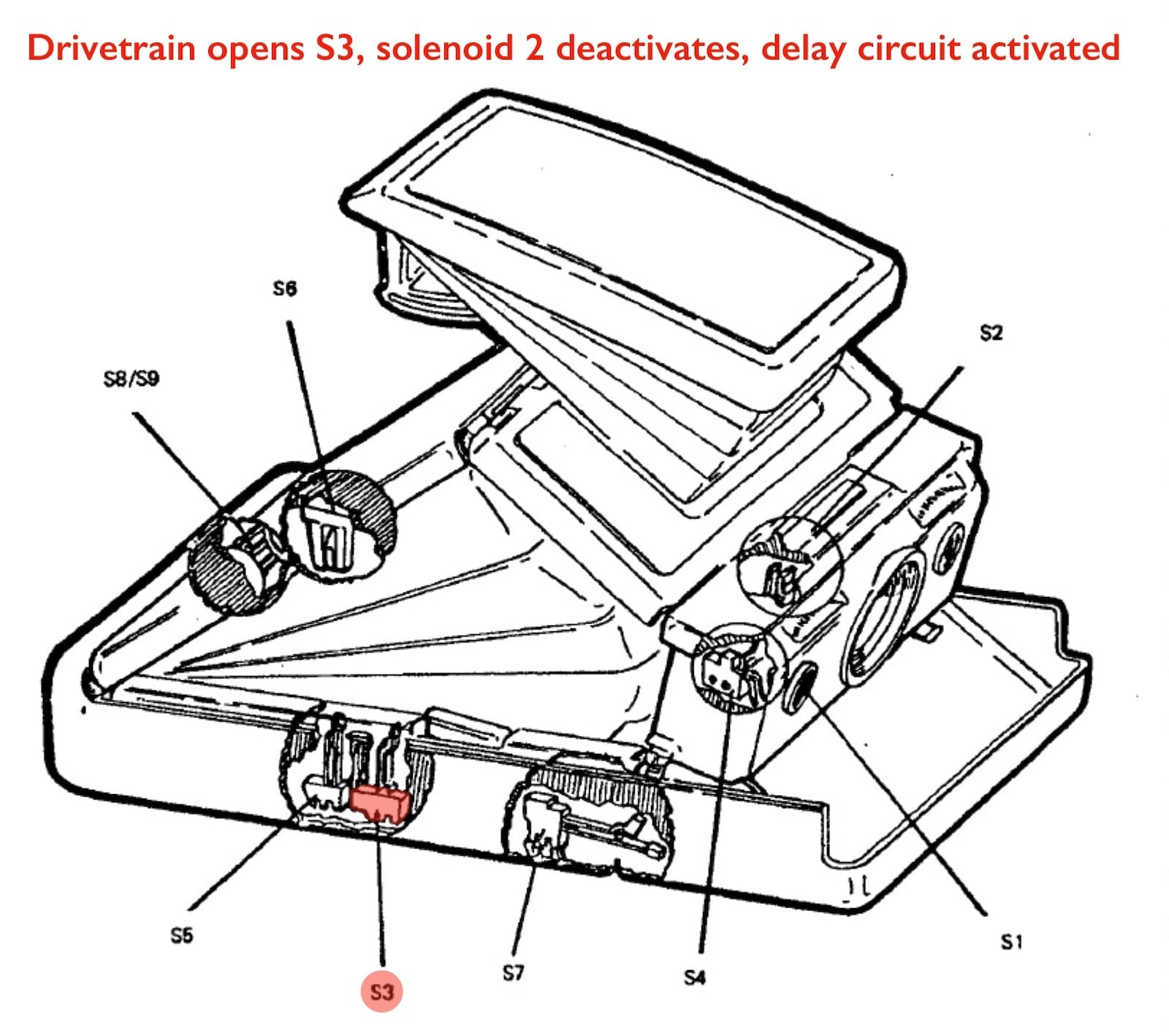
While the fresnel carrier was moving up prior to motor shutdown, the recheck ram opens switch S3. When S3 opens, it signals the ECM to initiate a 40-millisecond delay in the sequence. This amount of time prevents a picture from being taken until mirror bounce has subsided.
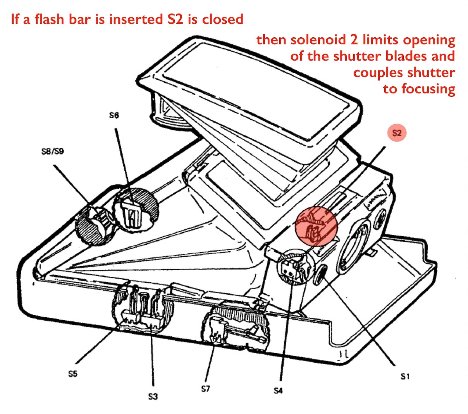
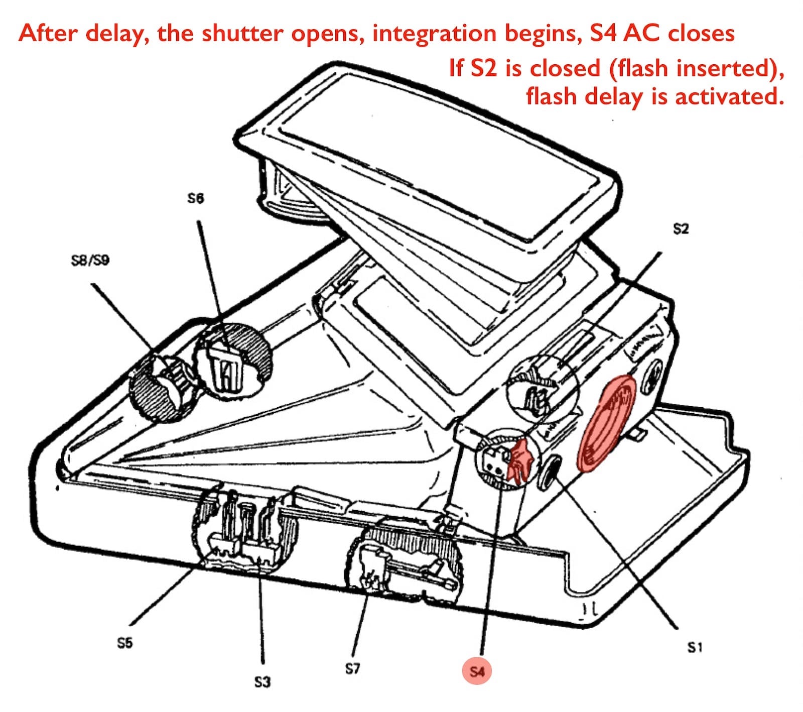
At the end of the 40 millisecond delay period, the ECM removes power from solenoid #1 and the shutter opens. Simultaneously, the circuit starts timing the exposure (integration). The integration components of the ECM are controlled by the amount of light received be the photocell.
At this same time, the flash delay section of the ECM is made ready but will not function unless a flashbar has been plugged in, to close switch S2.
When power is removed from solenoid #1 (and the shutter begins opening), the actuator on the plunger returns switch S4 to its original condition (CA closed). When the exposure timing cycle is complete, power is returned to solenoid #1 and the shutter closes, opening CA, closing CB, placing solenoid #1 again in the power down condition and starting the motor to eject the exposed film.
The length of the timing cycle is determined by the amount of light reaching the photocell. If there is insufficient light to correctly operate the integration circuits, the system will automatically terminate the exposure within 14 to 30 seconds.
When, in the previous step, the solenoid closes the shutter blades and the drive motor is energized, the gear train resumes its sequence with the following results:
If the operator has removed pressure from the exposure button all power will be removed and the shutter blades will open to permit viewing. If the button has not been released, the shutter blades will remain closed until the operator removes his finger from the button.
The diagrams used to create the sequence images and the text descriptions of the actions are all taken from the original SX-70 repair book.